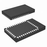
LMX9838SB/NOPB National Semiconductor, LMX9838SB/NOPB Datasheet - Page 23

LMX9838SB/NOPB
Manufacturer Part Number
LMX9838SB/NOPB
Description
IC MODULE BLUETOOTH PORT 70LTCC
Manufacturer
National Semiconductor
Datasheet
1.LMX9838DONGLE.pdf
(30 pages)
Specifications of LMX9838SB/NOPB
Frequency
2.4GHz
Data Rate - Maximum
704kbps
Modulation Or Protocol
Bluetooth v2.0, Class 2
Applications
PDA's, POS Terminals
Power - Output
0dBm
Sensitivity
-80dBm
Voltage - Supply
2.5 V ~ 3.6 V
Current - Receiving
65mA
Current - Transmitting
65mA
Data Interface
PCB, Surface Mount
Antenna Connector
On-Board, Chip
Operating Temperature
-40°C ~ 125°C
Package / Case
70-LTCC
Physical Interfaces
UART
Data Rate
704Kbps
Operating Temperature Range
-40°C To +85°C
Msl
MSL 4 - 72 Hours
Frequency Max
2480MHz
Filter Terminals
SMD
Frequency Min
2402MHz
No. Of Pins
70
Rohs Compliant
Yes
For Use With
LMX9838DONGLE - KIT DESIGN DONGLE FOR LMX9838
Lead Free Status / RoHS Status
Lead free / RoHS Compliant
Memory Size
-
Lead Free Status / Rohs Status
Compliant
Other names
LMX9838SB
Available stocks
Company
Part Number
Manufacturer
Quantity
Price
Company:
Part Number:
LMX9838SB/NOPB
Manufacturer:
NSC
Quantity:
560
Part Number:
LMX9838SB/NOPB
Manufacturer:
TI/德州仪器
Quantity:
20 000
17.0 Application Notes
The different possibilities to power supply the LMX9838 de-
pend on the IO interface logic level.
Figure 9 represents an example of system functional
schematic for the LMX9838 using a 3.0V to 3.3V IO interface.
Figure 10 represents an example of system functional
schematic for the LMX9838 using a 2.5V to 3.0V IO interface.
Figure 11 represents an example of system functional
schematic for the LMX9838 using a 1.8V to 2.5V IO interface.
Figure 12 represents an example of system functional
schematic for the LMX9838 using a 1.8V IO interface.
Capacitor values C1 and C2 may vary depending on design and crystal manufacturer specification.
FIGURE 9. 3.0V to 3.3V Example Functional System Schematic
Notes:
23
17.1 FILTERED POWER SUPPLY
It is important to provide the LMX9838 with adequate ground
planes and a filtered power supply. It is highly recommended
that a 2.2 μF and a 100 nF bypass capacitor be placed as
close as possible to the power supply pins V
V
17.2 FREQUENCY AND BAUDRATE SELECTION
OP3, OP4, OP5 can be strapped to the host logic 0 and 1
levels to set the host interface boot-up configuration. Alterna-
tively all OP3, OP4, OP5 can be hardwired over 1k Ohm
pullup/pulldown resistors. See Table 7.
CC
_IO.
30027908
CC
, MV
www.national.com
CC
, and


