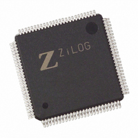
EZ80190AZ050EG Zilog, EZ80190AZ050EG Datasheet - Page 160

EZ80190AZ050EG
Manufacturer Part Number
EZ80190AZ050EG
Description
IC WEBSERVER 50MHZ XTEMP 100LQFP
Manufacturer
Zilog
Datasheet
1.EZ80190AZ050SG.pdf
(221 pages)
Specifications of EZ80190AZ050EG
Processor Type
eZ80
Features
High Speed, Single-Cycle Instruction-Fetch
Speed
50MHz
Voltage
3.3V
Mounting Type
Surface Mount
Package / Case
100-LQFP
Processor Series
EZ80190x
Core
eZ80
Data Bus Width
8 bit
Program Memory Type
ROMLess
Data Ram Size
8 KB
Interface Type
I2C, IrDA, SPI, UART
Maximum Clock Frequency
50 MHz
Number Of Programmable I/os
32
Number Of Timers
6
Operating Supply Voltage
3 V to 3.6 V
Maximum Operating Temperature
+ 70 C
Mounting Style
SMD/SMT
Minimum Operating Temperature
0 C
Lead Free Status / RoHS Status
Lead free / RoHS Compliant
Other names
269-3865
EZ80190AZ050EG
EZ80190AZ050EG
Available stocks
Company
Part Number
Manufacturer
Quantity
Price
Company:
Part Number:
EZ80190AZ050EG
Manufacturer:
TYCO
Quantity:
120
Company:
Part Number:
EZ80190AZ050EG
Manufacturer:
Zilog
Quantity:
70
- Current page: 160 of 221
- Download datasheet (4Mb)
ZDI Register Addressing
PS006614-1208
ZDI Single-Bit Byte Separator
ZCL
ZDA
Following each 8-bit ZDI data transfer, a single-bit byte separator is used. The ZDA pin
should be forced High (1) prior to the ZCL rising edge for this 9
ations, the ZDI register address automatically increments during this single-bit byte sepa-
rator period. The same read or write operation as just completed can then be immediately
performed on the next ZDI register. If a different operation or register address is required,
a ZDI START signal during the byte separator bit can be used to terminate the previous
read or write operation and signify initiation of a new ZDI register operation.
Following a START signal, the ZDI master must output the ZDI register address. All data
transfers with the ZDI block use special ZDI registers. The ZDI control registers that
reside in the ZDI register address space should not be confused with the eZ80190 device
peripheral registers that reside in the I/O addressing space of the eZ80190 device.
Many locations in the ZDI control register address space are shared by two registers, one
for Read Only access and one for Write Only access. As an example, a read from ZDI reg-
ister address
00h
points.
The format for a ZDI address is seven bits of address, followed by one bit for read or write
control, and completed by a single-bit byte separator in which ZDA must be 1. The data
separator time period is used to allow the ZDI master to send a new ZDI START signal, if
necessary. The ZDI executes a read or write operation depending on the state of the R/W
bit (0 = write, 1 = read).
Signal
Start
, stores the Low byte of one of the address match values used for generating break
S
msb
00h
A6
1
returns the Product ID Low Byte while a write to this same location,
A5
2
Figure 30
Figure 30. ZDI Address Write Timing
A4
3
ZDI Address Byte
displays the timing for address writes to ZDI registers.
A3
4
A2
5
A1
6
A0
lsb
7
0 = write
1 = read
R/W
th
Product Specification
8
bit. For most ZDI oper-
Byte Separator
START Signal
or new ZDI
Single-Bit
Zilog Debug Interface
1
9
eZ80190
150
Related parts for EZ80190AZ050EG
Image
Part Number
Description
Manufacturer
Datasheet
Request
R

Part Number:
Description:
Communication Controllers, ZILOG INTELLIGENT PERIPHERAL CONTROLLER (ZIP)
Manufacturer:
Zilog, Inc.
Datasheet:

Part Number:
Description:
KIT DEV FOR Z8 ENCORE 16K TO 64K
Manufacturer:
Zilog
Datasheet:

Part Number:
Description:
KIT DEV Z8 ENCORE XP 28-PIN
Manufacturer:
Zilog
Datasheet:

Part Number:
Description:
DEV KIT FOR Z8 ENCORE 8K/4K
Manufacturer:
Zilog
Datasheet:

Part Number:
Description:
KIT DEV Z8 ENCORE XP 28-PIN
Manufacturer:
Zilog
Datasheet:

Part Number:
Description:
DEV KIT FOR Z8 ENCORE 4K TO 8K
Manufacturer:
Zilog
Datasheet:

Part Number:
Description:
CMOS Z8 microcontroller. ROM 16 Kbytes, RAM 256 bytes, speed 16 MHz, 32 lines I/O, 3.0V to 5.5V
Manufacturer:
Zilog, Inc.
Datasheet:

Part Number:
Description:
Low-cost microcontroller. 512 bytes ROM, 61 bytes RAM, 8 MHz
Manufacturer:
Zilog, Inc.
Datasheet:

Part Number:
Description:
Z8 4K OTP Microcontroller
Manufacturer:
Zilog, Inc.
Datasheet:

Part Number:
Description:
CMOS SUPER8 ROMLESS MCU
Manufacturer:
Zilog, Inc.
Datasheet:

Part Number:
Description:
SL1866 CMOSZ8 OTP Microcontroller
Manufacturer:
Zilog, Inc.
Datasheet:

Part Number:
Description:
SL1866 CMOSZ8 OTP Microcontroller
Manufacturer:
Zilog, Inc.
Datasheet:

Part Number:
Description:
OTP (KB) = 1, RAM = 125, Speed = 12, I/O = 14, 8-bit Timers = 2, Comm Interfaces Other Features = Por, LV Protect, Voltage = 4.5-5.5V
Manufacturer:
Zilog, Inc.
Datasheet:

Part Number:
Description:
Manufacturer:
Zilog, Inc.
Datasheet:


